In offshore manufacturing, success begins long before production starts. It begins with the drawing. Learning how to prepare production-ready drawings for offshore manufacturing helps ensure that suppliers clearly understand your design intent before production begins.
When projects move from design into manufacturing, drawings become the primary tool that guides materials, machining, assembly, and quality control. In an offshore environment, where communication happens across countries, time zones, and teams, clarity in documentation becomes even more important.
Production-ready drawings help reduce delays, protect quality, and support accurate costing. They ensure that everyone involved shares the same understanding before metal is cut. Simply put, in offshore manufacturing, strong and well-prepared drawings create the foundation for a smoother, more efficient production process.
Common Drawing Issues Before Offshore Manufacturing
It’s more common than you might think:
- Missing or incomplete dimensions
- Tolerances not specified
- Material grade not specified
- Surface finishes undefined
- No welding symbols specified
- Critical notes missing
- Inconsistency between STEP files and PDF drawings
These types of issues often appear when design files move quickly from R&D into production without a structured process to prepare production-ready drawings for offshore manufacturing.
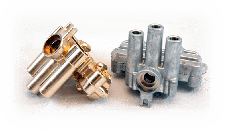
The latter is one of the biggest issues we see. The 3D model may show one dimension, while the 2D drawing specifies another. Hole sizes differ. Material thickness may be updated in one file but not the other.
An experienced offshore manufacturer can often detect these discrepancies early during the engineering production review. However, even seasoned teams can occasionally overlook minor inconsistencies — and sometimes these issues are not discovered until the Final Quality Assurance (QA) inspection stage.
Obviously, when this occurs, there can be a substantial waste of both money and time. In fact, in most cases the products need to be reworked or remade from scratch.
STEP File vs PDF Drawing: Why File Mismatches Cause Manufacturing Errors
In manufacturing, 3D and 2D files serve different — but equally important — purposes. They are not interchangeable, and both must communicate the same information clearly.
1️⃣ 3D Files: STEP, STL, SLDPRT/SLDASM

- STEP file (.step / .stp) → A neutral 3D CAD format used to transfer solid models between software platforms. It is commonly used for CNC programming, toolpath generation, and visual reference. This is the most common 3D CAD model used in manufacturing and is most likely the one your supplier will ask from you.
- STL file (.stl) → Mesh format. This is the most common file format for 3D printing. It only contains triangulated mesh and does not contain solids, or other metadata.
- SLDPRT/SLDASM files (.sldprt/.sldasm) → These are SolidWorks native files and are Fully parametric CAD files. They contain all features, materials, configurations and BOM data. They can be fully editable with full design history.
These files are typically used by engineers and programmers to generate machine instructions. However, they often do not carry full manufacturing intent — such as general tolerances, finishing requirements, or special notes — unless specifically embedded.
2️⃣ 2D Files: PDF, .DXF, .DWG

- PDF files are the official drawing format for specifying all the details of a particular component, assembly or product. They represent the formal manufacturing reference document and generally include all the following: Critical dimensions; tolerances (general and specific); Material specifications; Surface finish requirements (or Coating and treatment details); Welding symbols and standards; the revision history and any possible notes on manufacturing requirements.
- DXF files are what factories prefer for plasma or laser cutting, waterjet cutting and CNC routing, because they can be imported into CAM software easily. They are Text-based (ASCII) or binary and are designed for universal compatibility.
- DWG files are what designers and drafters work in. They are native CAD files, but similarly to dxf files, they are generally used for 2D CAD drawings. DWG files have full fidelity and preserve all CAD features: they can store layers, 3D solids, dynamic blocks and materials.
In most professional manufacturing environments, the 2D drawings govern the final requirements unless otherwise specified. The PDF drawing is treated as the authoritative and contractual document, whereas the STEP file is treated as the reference geometry.
Why having same details in these files is Critical
If the 3D model does not match the PDF drawing, production risks increase.
For example:
- A 3D model may show one thickness, while the PDF specifies another.
- A hole diameter may differ between the DXF cutting file and the drawing dimension.
- The model may not reflect the latest design revision shown on the PDF.
When working with overseas suppliers, small discrepancies can quickly become larger issues. Communication barriers, language differences, and time zone gaps mean there is less opportunity for quick clarification on the shop floor.
That’s why in offshore manufacturing, documentation clarity and consistency are essential. When 3D files and 2D drawings are fully aligned, production moves forward more seamlessly, with fewer delays, and with stronger quality control from start to finish.
Why Offshore Manufacturers Must Catch Discrepancies Early
In offshore manufacturing, timing matters.
If discrepancies between drawings are not identified early, they can become much bigger issues later in production.
Most assembled products, contain many components, and complex products can contain hundreds of components all having their own pdf drawing outlining all the specifications. During the production review stage, the factory engineers will review all the pdf drawings to make sure everything is clear and so they can proceed with purchasing all the material needed to fulfill the order.
When this review stage is rushed or not tightly managed, even experienced manufacturers may miss discrepancies, finding them only during:
- First Article Inspection (FAI)
- Trial assembly or
- Final Quality Assurance (QA)
The reason discrepancies are commonly found during these stages is that these are when the supplier is testing the relationship between items. If a part doesn’t fit, there may be a design problem that had been missed. Although pdf files are the main reference point for production, it could be that the factory used the CAD model for CNC machining. If the dimensions do not match the pdf file, this will most likely have to be remade or reworked.

What Offshore Manufacturers Check Before Production
When providing drawings to an overseas supplier, a strong technical team should always:
- Conduct detailed drawing checks before quoting
- Compare STEP files with PDF drawings
- Review tolerances for manufacturability and feasibility
- Assess weld symbols and surface treatment requirements
- Clarify any ambiguous or missing specifications
Early technical review is not about questioning the design — it’s about protecting the project. Catching discrepancies at the beginning ensures smoother production, better quality control, and stronger timeline performance in offshore manufacturing.
Why Late Design Changes Increase Offshore Manufacturing Costs
One of the most important principles in manufacturing is this:
It is always cheaper to make changes in planning than in production.
Changing a dimension in CAD takes minutes and the cost is minimal.
Reworking 500 fabricated parts can take weeks and can cost a considerable and unnecessary amount of money.
Late-stage changes can lead to:
- Scrapping and repurchase of material
- Reworking costs
- Shipping delays
- Production rescheduling
- Strained supplier relationships
Especially in offshore supply chains, correcting an issue after shipment can mean significant downtime for your operations.
How to Convert Planning Drawings into Production-Ready Drawings for Offshore Manufacturing
So what does it mean to prepare production-ready drawings for offshore manufacturing?
A production-ready drawing should include:
✔ Clear material specifications
✔ Complete dimensions
✔ Defined tolerances
✔ Surface finish requirements
✔ Coating instructions
✔ Weld symbols and standards
✔ Revision number and details
✔ Consistent in formation in drawings (CAD models, PDF Files)
It’s not about having a “perfect” R&D design — it’s about having a technically aligned design before manufacturing begins. (emphasize) you should not rush
Two mistakes that we often see from customers, are 1) Wanting to start production too early, before the drawings have been fully completed, or 2) Starting the conversation too late. Some design teams spend too much time on the design, and by the time they have their finalized drawing package, they have eaten into all their available lead time. This then leads them to push the supplier thus increasing the risk of error.
How Experienced Offshore Manufacturers Add Value
An experienced offshore manufacturing partner does more than just fabricate parts.
They:
- Perform technical drawing reviews before production
- Highlight inconsistencies early
- Suggest manufacturability improvements
- Recommend cost-saving adjustments
You may find it difficult to get design suggestions from suppliers. This might seem strange, but there is a clear reason. First of all, nobody knows the product like the person who designed it, and secondly it is a matter of responsibility. If a supplier proposes a design change that ends up not being to the customer’s satisfaction, there is the risk of falling out and worse.
However, at Dragon Metal Manufacturing, we are able to overcome this challenge and help our customers tap into decades of manufacturing experience and get suggestions to improve manufacturability, reduce costs and make packaging and container loading more cost-effective.
During the first sample approval process, we invite our customers to the factory to confirm their first samples and sign off on production. While we are all at the factory, it is the perfect time to review all possible ideas for improving the production cycle, from manufacturing to shipping.
This early involvement adds immense value to our customers, who often struggle getting advice or suggestions from anyone else, even other local Australian suppliers and design firms.

Manufacturing Drawing Checklist Before Sending to a Supplier
Before sending drawings to a manufacturer — whether local or offshore — it’s always worth doing a final review. A simple checklist can help prevent delays, reduce production risks, and ensure your documentation is ready for manufacturing.
Before releasing your drawings to a supplier, confirm that:
- STEP, DWG, or DXF files match the PDF drawing
Make sure the geometry and dimensions shown in the 3D CAD models are consistent with the official 2D drawing. - All critical tolerances are clearly defined
If tolerances are missing or unclear, the supplier may have to make assumptions that affect the final part quality. - Materials, grades, and surface finishes are specified
Clear material specifications and coating or finish requirements help ensure the parts meet the intended performance and durability standards. - Welding symbols and special notes are included where required
For fabricated assemblies, welding standards and notes are essential to avoid misinterpretation during production. - The latest revision number is shown on the PDF drawing
Revision control should be consistent across all files so the manufacturer is always working from the correct version.
Taking a few minutes to review these details can make a significant difference to the overall success of a manufacturing project. Clear and consistent documentation helps suppliers proceed with confidence and reduces the risk of delays or rework later in production.
Final Thoughts: Planning Is the Real Production hack
Manufacturing success doesn’t start on the factory floor. It starts in the planning phase.
Over the years, we’ve received projects at every stage of development — from early R&D concepts to fully production-ready documentation. No matter where you are in the process, strengthening your drawings before production begins can make a significant difference in cost, timelines, and product quality.
And if you ever need support beyond documentation — from technical review through to full offshore manufacturing production — our team is always ready to work alongside you and support the entire project from planning to delivery.